题目
多项填空题
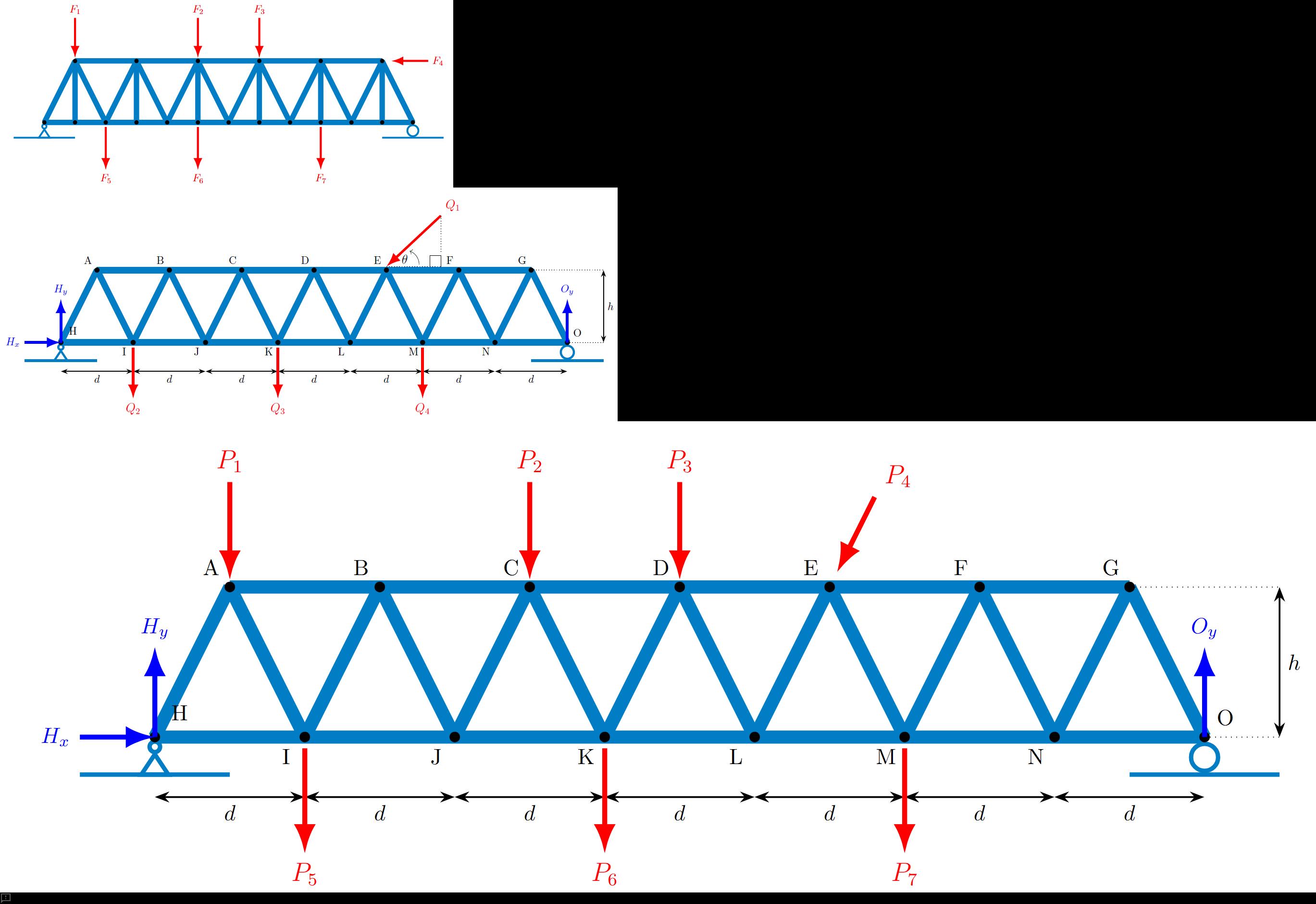
Question text 13Marks PROBLEM 3 Consider the truss shown below in Figure P3a. It is loaded with seven external forces, labelled [math: F1] F_1 to [math: F7] F_7 , acting at the nodes of the truss. The forces are all positive non-zero forces acting in the directions shown. Figure P3a. Truss with applied forces. (a) How many zero force members are there for this truss loading condition? (1 mark) Answer 1[input] zero-force members (b) Consider the same truss in Figure P3a (above). Select the best classification of its stability and determinacy by selecting from the options below. (1 mark) Answer 2[select: , Stable but statically indeterminate, Unstable and statically determinate, Stable and statically determinate, Unstable and statically indeterminate, Overconstrained but unstable] (c) Now consider the truss shown below in Figure P3b. It is loaded with four external forces, labelled [math: Q1] Q_1 to [math: Q4] Q_4 , acting at the nodes of the truss as shown. Determine the reaction forces [math: Hx] H_x and [math: Hy] H_y at the pin support at Node H, and the vertical reaction [math: Oy] O_y at the horizontal roller support, Node O. Note: all reactions are positive in the direction of x and y axes, respectively, and a counterclockwise moment is considered positive. (5 marks) [math: d=10m] d = 10 \, \text{m} [math: h=15m] h = 15 \, \text{m} [math: θ=40∘] \theta = 40^\circ [math: Q1=200kN] Q_1 = 200 \, \text{kN} [math: Q2=Q3=115kN] Q_2 = Q_3 = 115 \, \text{kN} [math: Q4=200kN] Q_4 = 200 \, \text{kN} Figure P3b. Truss with applied forces. Horizontal reaction at H ([math: Hx] H_x ) = Answer 3[input] kN Vertical reaction at H ([math: Hy] H_y ) = Answer 4[input] kN Vertical reaction at O ([math: Oy] O_y ) = Answer 5[input] kN (d) Now consider the same truss with different forces applied as shown in Figure P3c and listed below. Force [math: P4]P_4 is applied at Node E in the direction parallel with member EL, as shown in the figure. All other external forces are applied vertical (downwards) at the nodes. The reaction forces at the pin joint at H and the horizontal roller at O are provided to you for this loading configuration. (6 marks) Figure P3c. Truss with applied forces. [math: d=10m] d = 10 \, \text{m} [math: h=15m] h = 15 \, \text{m} [math: Hx=50kN] H_x = 50 \, \text{kN} [math: Hy=405.36kN] H_y = 405.36 \, \text{kN} [math: Oy=294.64kN] O_y = 294.64 \, \text{kN} [math: P1=P5=P6=P7=75kN] P_1 = P_5 = P_6 = P_7 = 75 \, \text{kN} [math: P2=P3=135kN] P_2 = P_3 = 135 \, \text{kN} [math: P4=158.11kN] P_4 = 158.11 \, \text{kN} Determine the forces in members DE, LE and LM. Force in member ([math: DE] ) = Answer 6[input] kN (2 marks) Force in member ([math: LE] ) = Answer 7[input] kN (2 marks) Force in member ([math: LM] ) = Answer 8[input] kN (2 marks) Notes Report question issue Question 3 Notes
查看解析
标准答案
Please login to view
思路分析
Let’s break down each part of Question 3 carefully and examine every option before identifying what the given answers imply. This will help you see why the selected values make sense and where other choices would lead you astray.
Part (a): How many zero-force members are there for this truss loading condition?
- Option A: “Two zero-force members.” If we apply standard zero-force member rules, a member connected to a joint with only two noncollinear members and no external load or support at that joint is zero-force. Similarly, at a joint with three members where two are collinear and there is no external load, the noncollinear member is zero. When inspecting the truss in Figure P3a under the seven applied forces (F1…F7) at the nodes, you look for joints that meet these criteria. If two such occurrences exist, two members would be zero. If not, the count would differ.
- Option B: “One zero-force member.” This would require only a single joint satisfying the two special cases above. Depending on the exact geometry and loading pattern, you may or may not get just one such instance.
- Option C: “Zero zero-force members.” This would imply every member carries some force under the given loading, which can happen if the load path forces every member to be active.
- Option D: “More than two zero-force members.” It’s possible in some symmetric or specific loading configurations to have multiple joints leading to multiple zero-force members, but yo......Login to view full explanation登录即可查看完整答案
我们收录了全球超50000道考试原题与详细解析,现在登录,立即获得答案。
类似问题
For the truss shown, determine by inspection whether the forces in AB, AC, BC, BD and BE are tensile, compressive or zero. The force in member AB is Blank 1 Question 5[select: , zero, compressive, tensile] The force in member AC is Blank 2 Question 5[select: , zero, compressive, tensile] The force in member BC is Blank 3 Question 5[select: , zero, compressive, tensile] The force in member BD is Blank 4 Question 5[select: , zero, compressive, tensile] The force in member BE is Blank 5 Question 5[select: , zero, compressive, tensile]
For the truss shown, calculate the force in member BD if P = 1097 N, a = 3.6 m, b = 2.1 m. Your answer should be positive for tension and negative for compression. Give your answer to two decimal places. Note: consider using method of sections.
A truss is subject to a point load P=849 N. Calculate the force in member BC (tension positive). Note: consider using method of sections.
Question text 13Marks Problem 3Consider the truss in Figure P3, which is supported on a pin at point A and a rocker/roller at point G. It is loaded with three horizontal forces [math: P=600] kN, [math: Q=200] kN, and [math: R=500] kN, and a vertical force [math: S=250] kN. The support reaction forces and their assumed directions are illustrated in the figure and their values are [math: Ax=−1300]A_x=-1300 kN, [math: Ay=−7500]A_y=-7500 kN, and [math: Gy=7750]G_y=7750 kN. Here, [math: H=3] m. Figure P3. Truss loaded with various point forces.a) Determine the number of zero-force members in the truss. [1 mark]Number of zero-force members = Answer 1[input]b) Determine the force in member DE. Use a positive value to indicate tension and a negative value to indicate compression. Provide your answer in kN to 4 decimal places. [2 marks]Force in member DE [kN] = Answer 2[input]c) Determine the force in member DC. Use a positive value to indicate tension and a negative value to indicate compression. Provide your answer in kN to 4 decimal places. [2 marks]Force in member DC [kN] = Answer 3[input]d) Determine the force in member BC. Use a positive value to indicate tension and a negative value to indicate compression. Provide your answer in kN to 4 decimal places. [2 marks]Force in member BC [kN] = Answer 4[input]e) Determine the force in member FE. Use a positive value to indicate tension and a negative value to indicate compression. Provide your answer in kN to 4 decimal places. [2 marks]Force in member FE [kN] = Answer 5[input]f) Determine the force in member BE. Use a positive value to indicate tension and a negative value to indicate compression. Provide your answer in kN to 4 decimal places. [2 marks]Force in member BE [kN] = Answer 6[input]g) Consider the case where the vertical load, S, is able to change. All other loads (P, Q, and R) remain the same. Determine the maximum allowable magnitude of S if support G can only manage a force magnitude of 20,000 kN. Provide your answer in kN to 4 decimal places. [2 marks]Maximum allowable magnitude of S [kN] = Answer 7[input]Notes Report question issue Question 3 Notes
更多留学生实用工具
希望你的学习变得更简单
加入我们,立即解锁 海量真题 与 独家解析,让复习快人一步!