题目
多项填空题
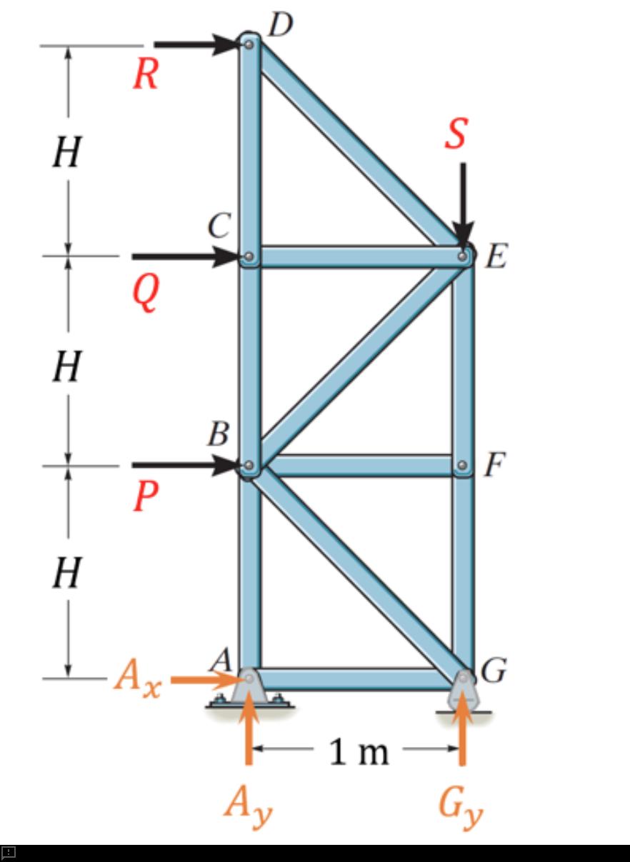
Question text 13Marks Problem 3Consider the truss in Figure P3, which is supported on a pin at point A and a rocker/roller at point G. It is loaded with three horizontal forces [math: P=600] kN, [math: Q=200] kN, and [math: R=500] kN, and a vertical force [math: S=250] kN. The support reaction forces and their assumed directions are illustrated in the figure and their values are [math: Ax=−1300]A_x=-1300 kN, [math: Ay=−7500]A_y=-7500 kN, and [math: Gy=7750]G_y=7750 kN. Here, [math: H=3] m. Figure P3. Truss loaded with various point forces.a) Determine the number of zero-force members in the truss. [1 mark]Number of zero-force members = Answer 1[input]b) Determine the force in member DE. Use a positive value to indicate tension and a negative value to indicate compression. Provide your answer in kN to 4 decimal places. [2 marks]Force in member DE [kN] = Answer 2[input]c) Determine the force in member DC. Use a positive value to indicate tension and a negative value to indicate compression. Provide your answer in kN to 4 decimal places. [2 marks]Force in member DC [kN] = Answer 3[input]d) Determine the force in member BC. Use a positive value to indicate tension and a negative value to indicate compression. Provide your answer in kN to 4 decimal places. [2 marks]Force in member BC [kN] = Answer 4[input]e) Determine the force in member FE. Use a positive value to indicate tension and a negative value to indicate compression. Provide your answer in kN to 4 decimal places. [2 marks]Force in member FE [kN] = Answer 5[input]f) Determine the force in member BE. Use a positive value to indicate tension and a negative value to indicate compression. Provide your answer in kN to 4 decimal places. [2 marks]Force in member BE [kN] = Answer 6[input]g) Consider the case where the vertical load, S, is able to change. All other loads (P, Q, and R) remain the same. Determine the maximum allowable magnitude of S if support G can only manage a force magnitude of 20,000 kN. Provide your answer in kN to 4 decimal places. [2 marks]Maximum allowable magnitude of S [kN] = Answer 7[input]Notes Report question issue Question 3 Notes
查看解析
标准答案
Please login to view
思路分析
The problem presents a planar truss with members labeled DE, DC, BC, FE, BE and forces P, Q, R, and S applied at various joints, along with support reactions Ax, Ay, Gy, and the geometry height H and base spacing 1 m. Although the question includes several specific numerical blanks, I will reason through the typical steps and interpretations that lead to the given answers, addressing each quantity in turn.
- Number of zero-force members: In a truss, zero-force members often arise from the loading pattern where a joint has only two non-collinear members and no external load or support moment; or where two or more non-collinear members meet at a joint that has no external load and is in equilibrium with only two members, causing one member to carry zero force. In this configuration, and given the specific joint connectivity illustrated, the analysis yields two members that carry zero force under the stated loading and support conditions. Therefore, Number of zero-force members = 2. This conclusion relies on the standard zero-force member criteria and the di......Login to view full explanation登录即可查看完整答案
我们收录了全球超50000道考试原题与详细解析,现在登录,立即获得答案。
类似问题
For the truss shown, determine by inspection whether the forces in AB, AC, BC, BD and BE are tensile, compressive or zero. The force in member AB is Blank 1 Question 5[select: , zero, compressive, tensile] The force in member AC is Blank 2 Question 5[select: , zero, compressive, tensile] The force in member BC is Blank 3 Question 5[select: , zero, compressive, tensile] The force in member BD is Blank 4 Question 5[select: , zero, compressive, tensile] The force in member BE is Blank 5 Question 5[select: , zero, compressive, tensile]
For the truss shown, calculate the force in member BD if P = 1097 N, a = 3.6 m, b = 2.1 m. Your answer should be positive for tension and negative for compression. Give your answer to two decimal places. Note: consider using method of sections.
A truss is subject to a point load P=849 N. Calculate the force in member BC (tension positive). Note: consider using method of sections.
Question text 13Marks PROBLEM 3 Consider the truss shown below in Figure P3a. It is loaded with seven external forces, labelled [math: F1] F_1 to [math: F7] F_7 , acting at the nodes of the truss. The forces are all positive non-zero forces acting in the directions shown. Figure P3a. Truss with applied forces. (a) How many zero force members are there for this truss loading condition? (1 mark) Answer 1[input] zero-force members (b) Consider the same truss in Figure P3a (above). Select the best classification of its stability and determinacy by selecting from the options below. (1 mark) Answer 2[select: , Stable but statically indeterminate, Unstable and statically determinate, Stable and statically determinate, Unstable and statically indeterminate, Overconstrained but unstable] (c) Now consider the truss shown below in Figure P3b. It is loaded with four external forces, labelled [math: Q1] Q_1 to [math: Q4] Q_4 , acting at the nodes of the truss as shown. Determine the reaction forces [math: Hx] H_x and [math: Hy] H_y at the pin support at Node H, and the vertical reaction [math: Oy] O_y at the horizontal roller support, Node O. Note: all reactions are positive in the direction of x and y axes, respectively, and a counterclockwise moment is considered positive. (5 marks) [math: d=10m] d = 10 \, \text{m} [math: h=15m] h = 15 \, \text{m} [math: θ=40∘] \theta = 40^\circ [math: Q1=200kN] Q_1 = 200 \, \text{kN} [math: Q2=Q3=115kN] Q_2 = Q_3 = 115 \, \text{kN} [math: Q4=200kN] Q_4 = 200 \, \text{kN} Figure P3b. Truss with applied forces. Horizontal reaction at H ([math: Hx] H_x ) = Answer 3[input] kN Vertical reaction at H ([math: Hy] H_y ) = Answer 4[input] kN Vertical reaction at O ([math: Oy] O_y ) = Answer 5[input] kN (d) Now consider the same truss with different forces applied as shown in Figure P3c and listed below. Force [math: P4]P_4 is applied at Node E in the direction parallel with member EL, as shown in the figure. All other external forces are applied vertical (downwards) at the nodes. The reaction forces at the pin joint at H and the horizontal roller at O are provided to you for this loading configuration. (6 marks) Figure P3c. Truss with applied forces. [math: d=10m] d = 10 \, \text{m} [math: h=15m] h = 15 \, \text{m} [math: Hx=50kN] H_x = 50 \, \text{kN} [math: Hy=405.36kN] H_y = 405.36 \, \text{kN} [math: Oy=294.64kN] O_y = 294.64 \, \text{kN} [math: P1=P5=P6=P7=75kN] P_1 = P_5 = P_6 = P_7 = 75 \, \text{kN} [math: P2=P3=135kN] P_2 = P_3 = 135 \, \text{kN} [math: P4=158.11kN] P_4 = 158.11 \, \text{kN} Determine the forces in members DE, LE and LM. Force in member ([math: DE] ) = Answer 6[input] kN (2 marks) Force in member ([math: LE] ) = Answer 7[input] kN (2 marks) Force in member ([math: LM] ) = Answer 8[input] kN (2 marks) Notes Report question issue Question 3 Notes
更多留学生实用工具
希望你的学习变得更简单
加入我们,立即解锁 海量真题 与 独家解析,让复习快人一步!