Questions
Numerical
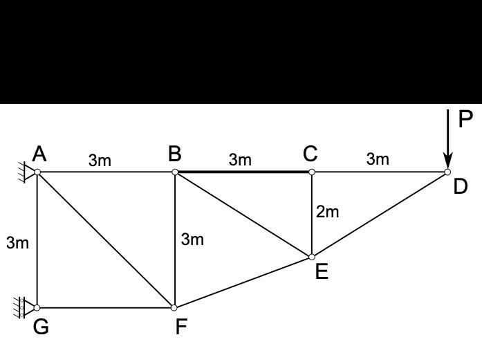
A truss is subject to a point load P=849 N. Calculate the force in member BC (tension positive). Note: consider using method of sections.
View Explanation
Verified Answer
Please login to view
Step-by-Step Analysis
First, parse the problem and identify that a method of sections is suggested for a truss subjected to a single external load P at point D. The goal is to determine the member force in BC with the convention that tension is positive.
Next, decide where to cut the truss. A common and convenient choice is to make a cut that passes through member BC and a couple of adjacent members so that the remaining left or right portion is in equilibrium with the external loads and reactions isolated. This keeps the algebra manageable by isolating BC in a single equilibrium equation.
Before cutting, note the key geometry and member orientations: AB, BC, and CD lie along the top chord with equal spacing, whi......Login to view full explanationLog in for full answers
We've collected over 50,000 authentic exam questions and detailed explanations from around the globe. Log in now and get instant access to the answers!
Similar Questions
For the truss shown, determine by inspection whether the forces in AB, AC, BC, BD and BE are tensile, compressive or zero. The force in member AB is Blank 1 Question 5[select: , zero, compressive, tensile] The force in member AC is Blank 2 Question 5[select: , zero, compressive, tensile] The force in member BC is Blank 3 Question 5[select: , zero, compressive, tensile] The force in member BD is Blank 4 Question 5[select: , zero, compressive, tensile] The force in member BE is Blank 5 Question 5[select: , zero, compressive, tensile]
For the truss shown, calculate the force in member BD if P = 1097 N, a = 3.6 m, b = 2.1 m. Your answer should be positive for tension and negative for compression. Give your answer to two decimal places. Note: consider using method of sections.
Question text 13Marks PROBLEM 3 Consider the truss shown below in Figure P3a. It is loaded with seven external forces, labelled [math: F1] F_1 to [math: F7] F_7 , acting at the nodes of the truss. The forces are all positive non-zero forces acting in the directions shown. Figure P3a. Truss with applied forces. (a) How many zero force members are there for this truss loading condition? (1 mark) Answer 1[input] zero-force members (b) Consider the same truss in Figure P3a (above). Select the best classification of its stability and determinacy by selecting from the options below. (1 mark) Answer 2[select: , Stable but statically indeterminate, Unstable and statically determinate, Stable and statically determinate, Unstable and statically indeterminate, Overconstrained but unstable] (c) Now consider the truss shown below in Figure P3b. It is loaded with four external forces, labelled [math: Q1] Q_1 to [math: Q4] Q_4 , acting at the nodes of the truss as shown. Determine the reaction forces [math: Hx] H_x and [math: Hy] H_y at the pin support at Node H, and the vertical reaction [math: Oy] O_y at the horizontal roller support, Node O. Note: all reactions are positive in the direction of x and y axes, respectively, and a counterclockwise moment is considered positive. (5 marks) [math: d=10m] d = 10 \, \text{m} [math: h=15m] h = 15 \, \text{m} [math: θ=40∘] \theta = 40^\circ [math: Q1=200kN] Q_1 = 200 \, \text{kN} [math: Q2=Q3=115kN] Q_2 = Q_3 = 115 \, \text{kN} [math: Q4=200kN] Q_4 = 200 \, \text{kN} Figure P3b. Truss with applied forces. Horizontal reaction at H ([math: Hx] H_x ) = Answer 3[input] kN Vertical reaction at H ([math: Hy] H_y ) = Answer 4[input] kN Vertical reaction at O ([math: Oy] O_y ) = Answer 5[input] kN (d) Now consider the same truss with different forces applied as shown in Figure P3c and listed below. Force [math: P4]P_4 is applied at Node E in the direction parallel with member EL, as shown in the figure. All other external forces are applied vertical (downwards) at the nodes. The reaction forces at the pin joint at H and the horizontal roller at O are provided to you for this loading configuration. (6 marks) Figure P3c. Truss with applied forces. [math: d=10m] d = 10 \, \text{m} [math: h=15m] h = 15 \, \text{m} [math: Hx=50kN] H_x = 50 \, \text{kN} [math: Hy=405.36kN] H_y = 405.36 \, \text{kN} [math: Oy=294.64kN] O_y = 294.64 \, \text{kN} [math: P1=P5=P6=P7=75kN] P_1 = P_5 = P_6 = P_7 = 75 \, \text{kN} [math: P2=P3=135kN] P_2 = P_3 = 135 \, \text{kN} [math: P4=158.11kN] P_4 = 158.11 \, \text{kN} Determine the forces in members DE, LE and LM. Force in member ([math: DE] ) = Answer 6[input] kN (2 marks) Force in member ([math: LE] ) = Answer 7[input] kN (2 marks) Force in member ([math: LM] ) = Answer 8[input] kN (2 marks) Notes Report question issue Question 3 Notes
Question text 13Marks Problem 3Consider the truss in Figure P3, which is supported on a pin at point A and a rocker/roller at point G. It is loaded with three horizontal forces [math: P=600] kN, [math: Q=200] kN, and [math: R=500] kN, and a vertical force [math: S=250] kN. The support reaction forces and their assumed directions are illustrated in the figure and their values are [math: Ax=−1300]A_x=-1300 kN, [math: Ay=−7500]A_y=-7500 kN, and [math: Gy=7750]G_y=7750 kN. Here, [math: H=3] m. Figure P3. Truss loaded with various point forces.a) Determine the number of zero-force members in the truss. [1 mark]Number of zero-force members = Answer 1[input]b) Determine the force in member DE. Use a positive value to indicate tension and a negative value to indicate compression. Provide your answer in kN to 4 decimal places. [2 marks]Force in member DE [kN] = Answer 2[input]c) Determine the force in member DC. Use a positive value to indicate tension and a negative value to indicate compression. Provide your answer in kN to 4 decimal places. [2 marks]Force in member DC [kN] = Answer 3[input]d) Determine the force in member BC. Use a positive value to indicate tension and a negative value to indicate compression. Provide your answer in kN to 4 decimal places. [2 marks]Force in member BC [kN] = Answer 4[input]e) Determine the force in member FE. Use a positive value to indicate tension and a negative value to indicate compression. Provide your answer in kN to 4 decimal places. [2 marks]Force in member FE [kN] = Answer 5[input]f) Determine the force in member BE. Use a positive value to indicate tension and a negative value to indicate compression. Provide your answer in kN to 4 decimal places. [2 marks]Force in member BE [kN] = Answer 6[input]g) Consider the case where the vertical load, S, is able to change. All other loads (P, Q, and R) remain the same. Determine the maximum allowable magnitude of S if support G can only manage a force magnitude of 20,000 kN. Provide your answer in kN to 4 decimal places. [2 marks]Maximum allowable magnitude of S [kN] = Answer 7[input]Notes Report question issue Question 3 Notes
More Practical Tools for Students Powered by AI Study Helper
Making Your Study Simpler
Join us and instantly unlock extensive past papers & exclusive solutions to get a head start on your studies!