Questions
FA25 ECE 555 001 Final
Multiple fill-in-the-blank
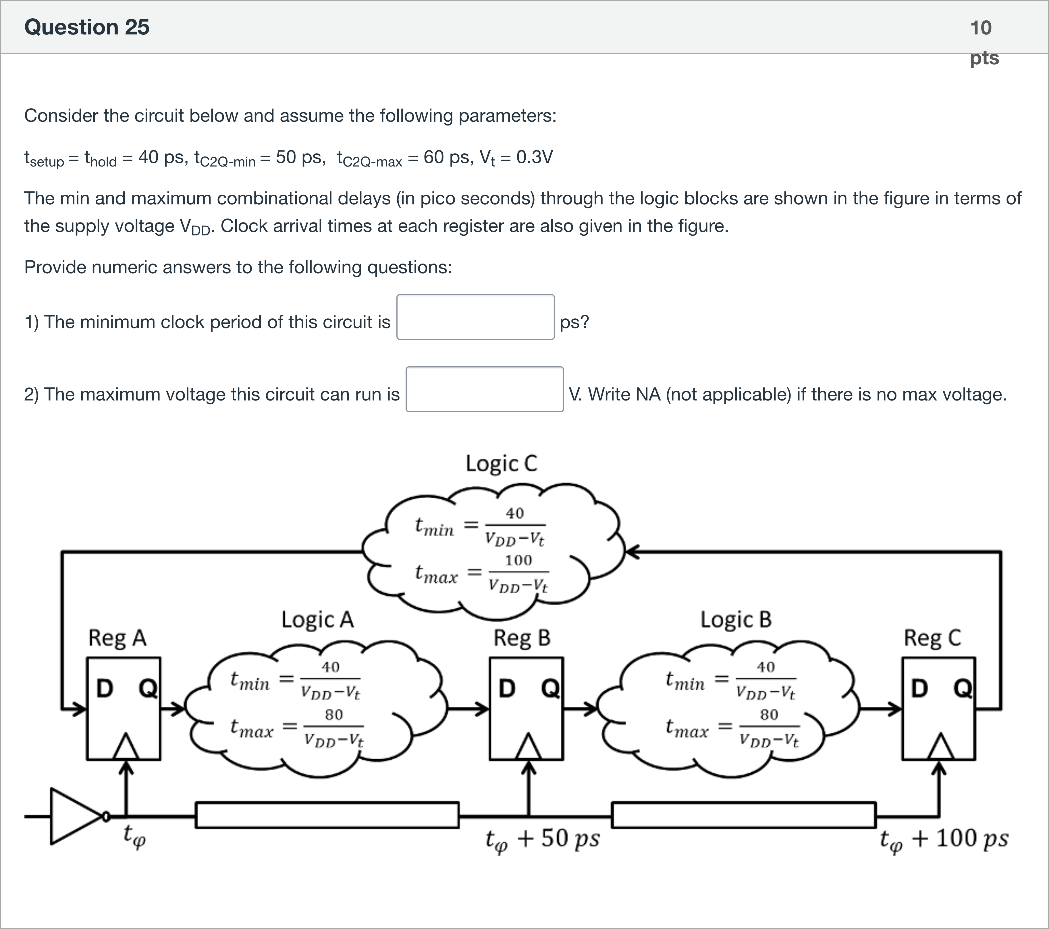
Consider the circuit below and assume the following parameters: tsetup = thold = 40 ps, tC2Q-min = 50 ps, tC2Q-max = 60 ps, Vt = 0.3V The min and maximum combinational delays (in pico seconds) through the logic blocks are shown in the figure in terms of the supply voltage VDD. Clock arrival times at each register are also given in the figure. Provide numeric answers to the following questions: 1) The minimum clock period of this circuit is [Fill in the blank] ps? 2) The maximum voltage this circuit can run is [Fill in the blank] V. Write NA (not applicable) if there is no max voltage.
View Explanation
Verified Answer
Please login to view
Step-by-Step Analysis
We begin by restating the problem setup and the data given, then proceed to analyze how the two requested quantities are determined from the timing constraints of the circuit.
- Known parameters: t_setup = t_hold = 40 ps, tC2Q-min = 50 ps, tC2Q-max = 60 ps, Vt = 0.3 V. The diagram indicates that the minimum combinational delay through each logic block is t_min = 40 / (VDD − Vt) and the maximum combinational delay through each logic block is t_max = 80 / (VDD − Vt) (note the factor 80 for the max case as shown in the figure). The clock arrival times at registers are provided in the schematic as well, which affects how the clock period and the maximum operating voltage are computed.
Option analysis for Question 1: The minimum clock period of this circuit is ______ ps
- Step 1: Recall the standard setup/hold timing relation for a synchronous circuit with registers in a single-clock domain. The minimum clock period is governed by the fast (minimum) path from one register’s Q output, through the combinational logic, to the next register’s D input, plus the......Login to view full explanationLog in for full answers
We've collected over 50,000 authentic exam questions and detailed explanations from around the globe. Log in now and get instant access to the answers!
Similar Questions
Assume the required time at output f is 5.80. Please calculate the required time for x and the origin. Note: The value inside the circle represents the delay of the gate. The value around the edge represents the delay of the wire. Required time for x: [Fill in the blank], Required time for origin: [Fill in the blank],
Consider the following setup timing report. Fill in the boxes 1 and 2 with the right numerical values (keep 3 decimal places). 1 [Fill in the blank], 2 [Fill in the blank],
In a consumer society, many adults channel creativity into buying things
Economic stress and unpredictable times have resulted in a booming industry for self-help products
More Practical Tools for Students Powered by AI Study Helper
Making Your Study Simpler
Join us and instantly unlock extensive past papers & exclusive solutions to get a head start on your studies!