Questions
ENGR-217:201,202,203,204,501,502,505,506,515,516,521,522,523,524,525,526,535,536,PHYS-217:203,204,501,502,503,531,532,533 pre-class_test_wk_12_Inductance; RL, LC, and RLC Circuits
Multiple choice
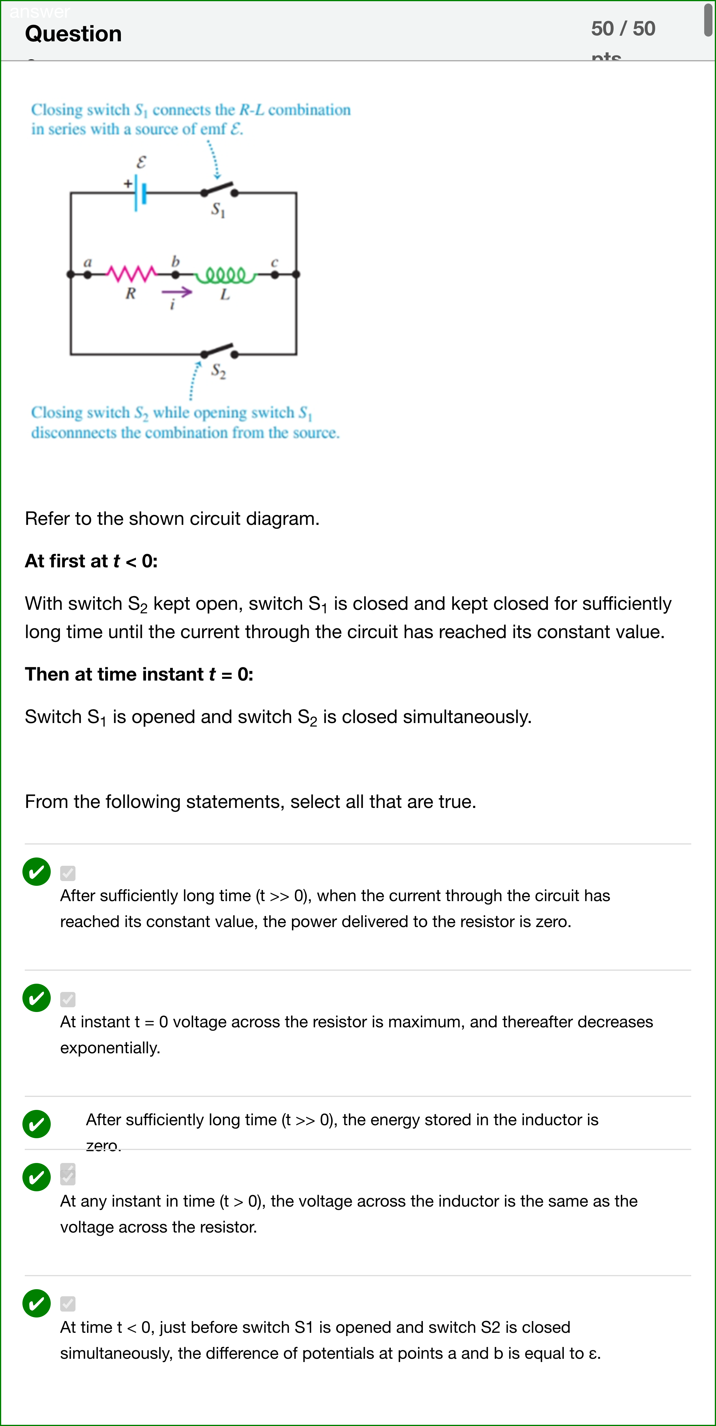
Refer to the shown circuit diagram. At first at t < 0: With switch S2 kept open, switch S1 is closed and kept closed for sufficiently long time until the current through the circuit has reached its constant value. Then at time instant t = 0: Switch S1 is opened and switch S2 is closed simultaneously. From the following statements, select all that are true.
View Explanation
Verified Answer
Please login to view
Step-by-Step Analysis
Let’s dissect the circuit behavior step by step for the two phases: t < 0 (steady state with S2 open, S1 closed) and t = 0 followed by t > 0 (S1 opened, S2 closed).
Option A: After sufficiently long time (t >> 0), when the current through the circuit has reached its constant value, the power delivered to the resistor is zero.
- When t >> 0 after switching, the inductor current decays to zero and there is no supply connected to the R-L loop (the source is d......Login to view full explanationLog in for full answers
We've collected over 50,000 authentic exam questions and detailed explanations from around the globe. Log in now and get instant access to the answers!
Similar Questions
In a consumer society, many adults channel creativity into buying things
Economic stress and unpredictable times have resulted in a booming industry for self-help products
People born without creativity never can develop it
A product has a selling price of $20, a contribution margin ratio of 40% and fixed cost of $120,000. To make a profit of $30,000. The number of units that must be sold is: Type the number without $ and a comma. Eg: 20000
More Practical Tools for Students Powered by AI Study Helper
Making Your Study Simpler
Join us and instantly unlock extensive past papers & exclusive solutions to get a head start on your studies!