Questions
4520_COMP_SCI_X_0005 Practice Exam
Single choice
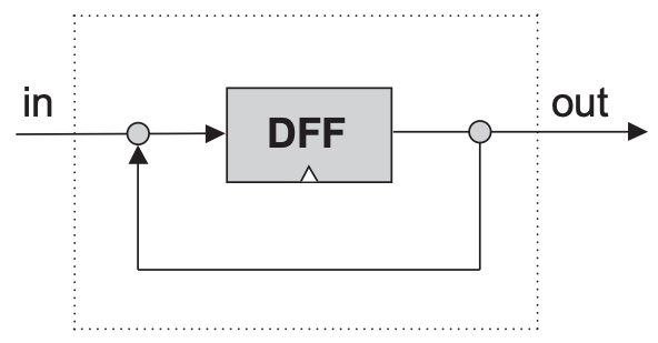
Category: Combinational Logic While it is OK to split an input signal into two wires it is problematic to just join two output signals on two wires without using a gate . Why is this the case? (for reference consider this diagram of the DFF gate in figure 3.1 in the textbook)
Options
A.It is problematic because such diagrams are hard to read and code.
B.It is problematic when the two outputs to be joined are different, then the signal produced is indeterminate.
C.It is problematic because it is physically impossible to join two output wires together
View Explanation
Verified Answer
Please login to view
Step-by-Step Analysis
Topic: joining two output signals on the same wire without a gate in a combinational logic context.
Option 1: 'It is problematic because such diagrams are hard to read and code.' This rationale focuses on readability or implementation style, not on the electrical or logical behavior of signals. The core issue is not readability but what happe......Login to view full explanationLog in for full answers
We've collected over 50,000 authentic exam questions and detailed explanations from around the globe. Log in now and get instant access to the answers!
Similar Questions
What is the logic function of F implemented by the circuit below?
'Static' in Static CMOS logic is used to emphasize:
A programmer wants you to develop the logic for a program they are building. The program is an attendance system which registers attendees in the following states: Present: The person is expected to come to work and has come to work Absent: The person is expected to come to work but did not come to work Present but applied for leave: The person is NOT expected to come to work but has come to work Absent and applied for leave: The person is NOT expected to come to work and has applied for leave To simplify the logic, the programmer has made FOUR switches, each with TWO possible states corresponding to the above 4 cases:1. Present Status (P):a. 0 = Absentb. 1 = Present2. Leave Status (L):a. 0 = Leave NOT appliedb. 1 = Leave applied3. Many Consecutive Days Missed (M):a. 0 = Less than 3 consecutive days missedb. 1 = 3 or more consecutive days missed4. Total Attendance (T):a. 0 = Less than 50% attendanceb. 1 = Equal or above 50% attendance You are expected to design the logic for a “Warning” system (X = 1) which will flag any person with the following states (conditions):1. The person is absent with no leave and has more than 3 consecutive days missed2. The person is present but has leave applied for that day3. The person has less than 50% attendanceDesign a logic network diagram that resolves the given conditions. a). Define the Truth Tableb). Use a Karnaugh Map to show the simplification of the circuit designc). Draw a logic circuitTip: Pay close attention to the values in the options and select the most appropriate answers that satisfies the above three questions. (a,b,c).Tip: You only need to select the correct option below. No need to submit or upload any of your workings.
How many possible input combinations are there for a logic gate with 3 inputs?
More Practical Tools for Students Powered by AI Study Helper
Making Your Study Simpler
Join us and instantly unlock extensive past papers & exclusive solutions to get a head start on your studies!