Questions
4520_COMP_SCI_X_0005 Practice Exam
Single choice
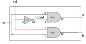
Category: Combinational Logic Consider the following diagram for a DMUX where the unselected output wire is set to zero. Would a Dmux still be a useful chip if this value was always set to 1? If yes, why, if not, why not?
Options
A.No. It would render the dmux useless because all of the rest of the machine would be expecting a zero in this place rather than a one and there is nothing we could do to fix it.
B.Yes. It doesn't matter what is on this output.
C.Yes. You might have to invert this signal or change the expected interpretation of this signal.
D.No. The ones make the output of the dmux unpredictable.
View Explanation
Verified Answer
Please login to view
Step-by-Step Analysis
Category: Combinational Logic
First, restating the scenario in my own words helps set the stage: we’re looking at a DMUX (demultiplexer) diagram where the unselected output wire is normally set to zero. The question asks whether the DMUX would still be useful if that unselected output wire were always set to 1, and to justify either why it would remain useful or why not.
Option 1: No. It would render the dmux useless because all of the rest of the machine would be expecting a zero in this place rather than a one and there is nothing we could do to fix it.
This choice argues that forcing the unused output to 1 breaks the expectations of downstream circuitry, which typically assumes a 0 on the unused path to indicate an inactive or non-selected channel. The claim that there is “nothing we coul......Login to view full explanationLog in for full answers
We've collected over 50,000 authentic exam questions and detailed explanations from around the globe. Log in now and get instant access to the answers!
Similar Questions
What is the logic function of F implemented by the circuit below?
'Static' in Static CMOS logic is used to emphasize:
A programmer wants you to develop the logic for a program they are building. The program is an attendance system which registers attendees in the following states: Present: The person is expected to come to work and has come to work Absent: The person is expected to come to work but did not come to work Present but applied for leave: The person is NOT expected to come to work but has come to work Absent and applied for leave: The person is NOT expected to come to work and has applied for leave To simplify the logic, the programmer has made FOUR switches, each with TWO possible states corresponding to the above 4 cases:1. Present Status (P):a. 0 = Absentb. 1 = Present2. Leave Status (L):a. 0 = Leave NOT appliedb. 1 = Leave applied3. Many Consecutive Days Missed (M):a. 0 = Less than 3 consecutive days missedb. 1 = 3 or more consecutive days missed4. Total Attendance (T):a. 0 = Less than 50% attendanceb. 1 = Equal or above 50% attendance You are expected to design the logic for a “Warning” system (X = 1) which will flag any person with the following states (conditions):1. The person is absent with no leave and has more than 3 consecutive days missed2. The person is present but has leave applied for that day3. The person has less than 50% attendanceDesign a logic network diagram that resolves the given conditions. a). Define the Truth Tableb). Use a Karnaugh Map to show the simplification of the circuit designc). Draw a logic circuitTip: Pay close attention to the values in the options and select the most appropriate answers that satisfies the above three questions. (a,b,c).Tip: You only need to select the correct option below. No need to submit or upload any of your workings.
How many possible input combinations are there for a logic gate with 3 inputs?
More Practical Tools for Students Powered by AI Study Helper
Making Your Study Simpler
Join us and instantly unlock extensive past papers & exclusive solutions to get a head start on your studies!